Servo Controller Status
OK! Here’s the back story amd statis for developing my servo controller project.
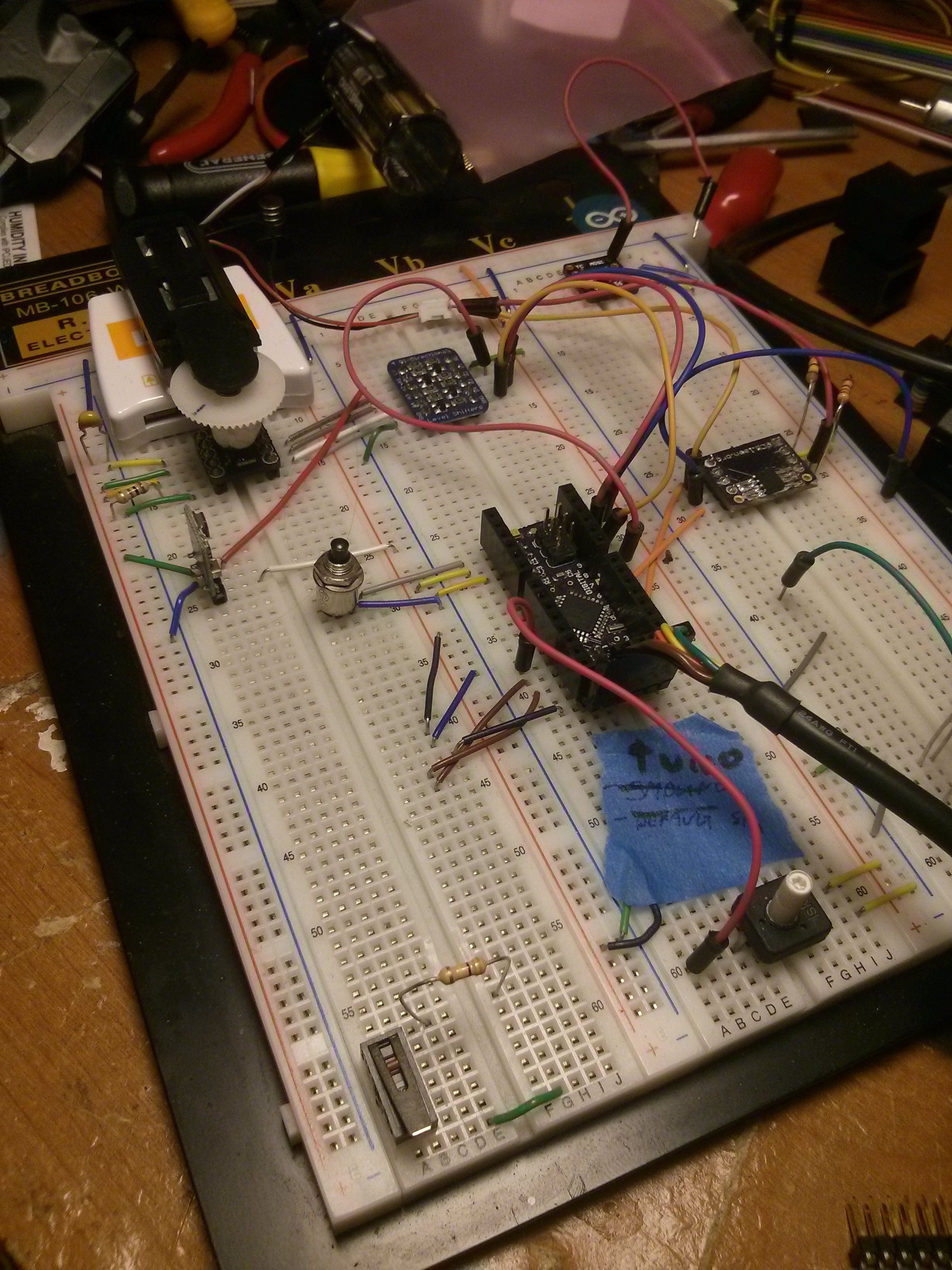
This is the first mockup of the whole system, after I decided that I needed to start this. The goal here was to simply read the AS5050 magnetic encoder, but it’s also been a very handy check when I screw up a board revision. Since everything is on breakouts, it let’s me quickly see where else I’ve totally botched my routing. Plus, it’s served as a “known good” for the code. Once this was working, I sent a board off to OSH Park, and enthusiastically waited two weeks, and then put the whole project off to the side for some 6 months. :(
 Eventually I did wrangle up a need to finish it, so I started laying out my V1 board. The first thing I needed to do was actually figure out a footprint to put the board in, so I used a bench grinder, drill press, and a bvit of yelling to figure out where the physical feautures needed to be. I used this data to modify the OpenServo board board outline, which wasn’t quite right for the servos I have.
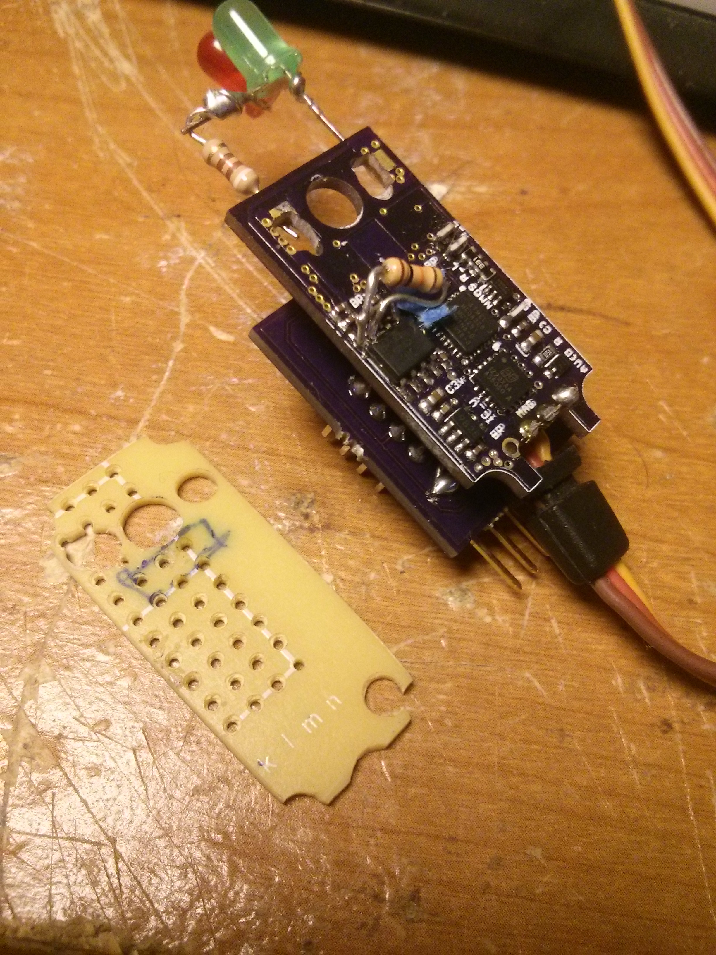
Actualy building this project taught me the value of a good stencil, sind I didn’t use one. This was painstakingly done with a syringe, cramped hands, and some fine surface mount rework to remove shorts. For reference, there’s 2 bidirectional level shifters, an encoder IC, atmega328, big honkin mosfet, and voltage regulators, all of which fit on a quarter. Routing was a bit intense, considering it was my first serious design.
On the plus side, it DID work! Not optimally, but it does. The massive resistor you see is because I forgot pull downs on the mosfet, and I was getting shoot through while trying to program the chip. That caused quite a bit of burned fingers while trying to figure that out. Throughout this project I’ve learned a whole bunch of practical FET handling practices.
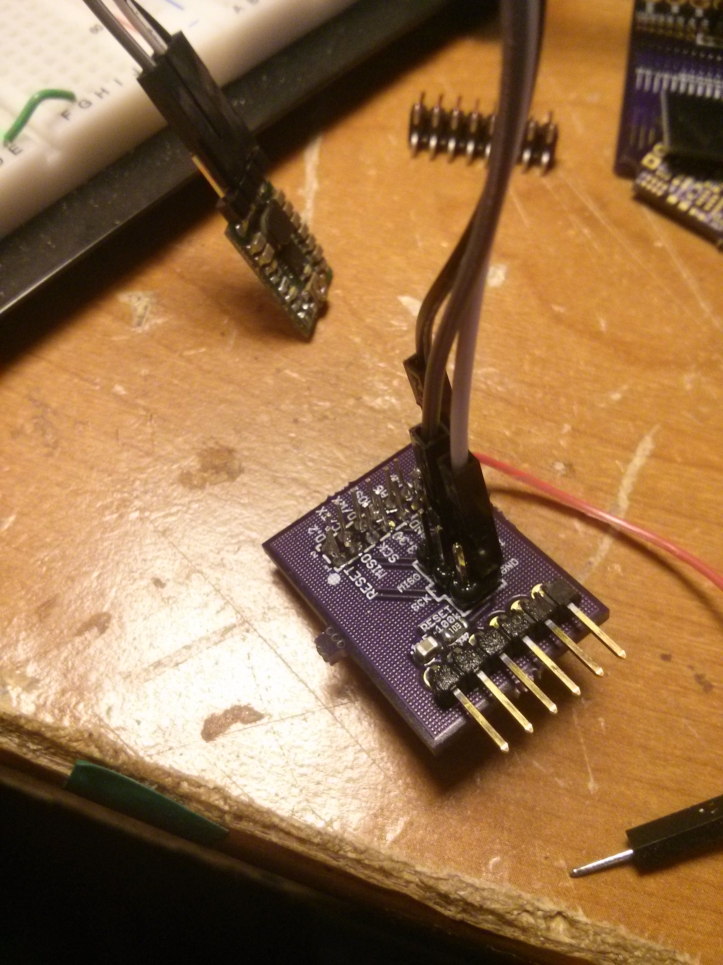 You can also see the secondary board hanging off of this, which is my programming board. When working on the routing, I realized
- I have lots of extra IO, and
- I need some way to program this that doesn’t drive me insane
My initial thought was using pogo pins, which would work, but fails requirement 2. The better option was adding a permanent breakout to the back, that was exposed through the back of the servo. This handily converts the whole project from an “arduino powered servo” to an “arduino-in-a-box”, which makes it stellar for a whole slew of home automation things. It also lets me program it easier. This did NOT simplify routing though, but is such an advantage that it’s totally worth it.
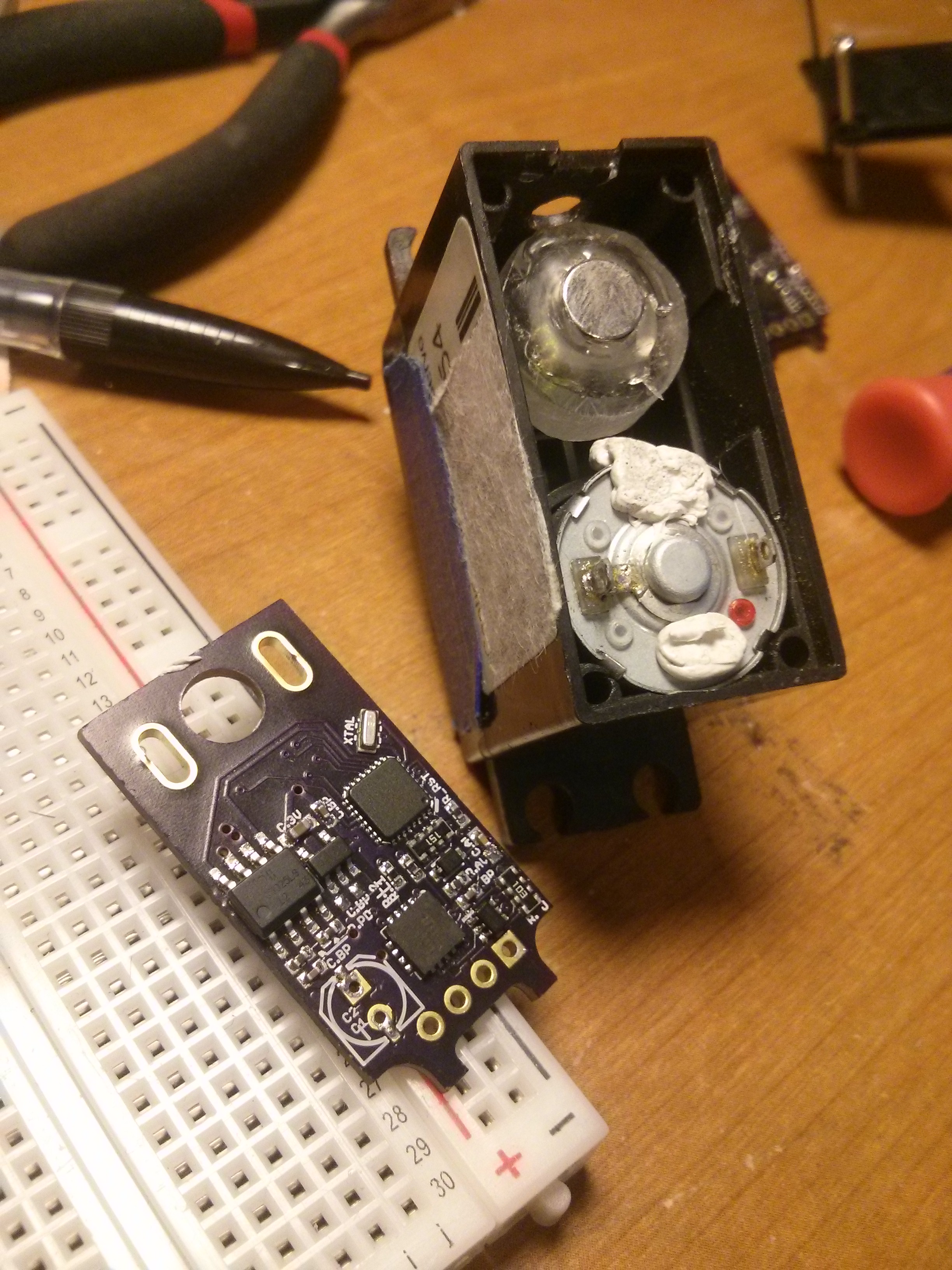
Andhere’s the current revision, alongside it’s home. It’s mostly the same as the previous board, but with improved routing, higher density, a place for a power capacitor, and importantly, was built with a stencil. I also modified the board to include slots, enlarge the motor hole, and relocate things.
The enclosure is a Parallax Continous Rotation servo with a small bolt glued to the output shaft, and a piece of acrylic and hot glue attached for supporting the magnet. Conveniently, the shafts are EXACTLY the right spacing for me to slide them onto the motor, and not have to solder them. So, I use poster tack to hold it in place when performing tests.
So far, I have only one interesting program written, which is a small clock. Basically, I just rotate the output shaft 1/60th a turn every second. Not quite perfect, but it’s great for figuring out bugs in my AS5050 library.